Tuesday, April 5, 2011

What is SOPEP????

 What is SOPEP? State the main element of SOPEP?

Shipboard Oil Pollution Emergency Plan (SOPEP).
MARPOL 73/78 Annex 1 Regulation 37 – Every ship of 400tons gross tonnage and above  and every oil tanker of 150 ton gross tonnage and above shall carry on board a Shipboard oil Pollution Emergency Plan approved by the administration.
The purpose of SOPEP is to provide guidance on the steps to be taken in the event of oil pollution incident.

The plans contains:
The procedure to be followed by the master or other person incharge of the ship to report an oil pollution incident.
The list of authorities or person to be contacted in the event of an oil pollution incident (Designated person).
A detailed description of the action to be taken immediately by person on board to reduce or control the discharge of oil following an accident.
The procedure and point of contact on the ship for coordinating shipboard action with national and local authorities in combating the pollution.


For easy reference, the following plans must be included in SOPEP

Principal particular of the vessel
General arrangement Plan
Capacity plan
Midships section
Shell Expansion plan
Pumping arrangement.

SOPEP to be kept with the Master and Chief Engineer. For it to be effective, it is important that all officers familiarise themselves with the plan. The practice drill and exercises to be carried out in order to reduce error and oversight and to save time and thus reduce the effects of an oil spill.


SHIPBOARD OIL POLLUTION EMERGENCY PLAN – SUMMARY FLOWCHART

This flow diagram is an outline of the course of action that shipboard personnel should follow in responding to an oil pollution emergency based on the guidelines published by the Organization. This diagram is not exhaustive and should not be used as a sole reference in response. Consideration should be given for inclusion of specific reference to the Plan. The steps are designed to assist ship personnel in action to stop or minimize the discharge of oil and mitigate its effects. These steps fall into two main categories – reporting and action.

Discharge of Oil
Probable or Actual
 
Assessment of the Nature of Incident
 
Actions required  
Alert crew members
Identity spill source
Spill assessment


REPORTING ACTION TO CONTROL DISCHARGE  
By Master and/ or designated crew member Measures to minimize the escape of oil and threat to the marine environment  
When to report
All probable and actual spills

How to report
- By quickest means to coastal radio station
- Designated ship movement reporting station or
- Rescue Co-ordination Centre (at sea)
- By quickest available means to local authorities

Who to report
- Nearest Coastal State Harbour and termi-nal operators (in port)
- Shipowner´s manager; P & I insurer
- Head Charterer; Cargo owner
- Refer to contact lists

What to report
- Initial report (Res. A.851(20))
- Follow-up reports
- Characteristics of oil spilled
- Cargo/ ballast/ bunker dispositions
- Weather and sea conditions
- Slick movement
- Assistance required
· Salvage
· Lightening capacity
· Mechanical equipment
· External strike team
· Chemical dispersant/ degreasant NAVIGATION MEASURES

- Alter course/ position and/ or speed
- Change of list and/ or trim
- Anchoring
- Setting aground
- Inititate towage
- Assess safe haven require-ments
- Weather/ tide/ swell fore-casting
- Slick monitoring
- Record of events and commu-nications taken SEAMANSHIP MEASURES

- Safety assessment and pre-caution
- Advice on priority countermea-sures/ preventive measures
- Damage stability and stress consideration
- Ballasting/ deballasting
- Internal cargo transfer opera-tions
- Emergency ship-to-ship trans-fers of cargo and/ or bunker
- Set up shipboard response for:
· Leak sealing
· Fire fighting
· Handling of ship-board response equipment (if available)
· Etc.  
 
STEPS TO INITIATE EXTERNAL RESPONSE  
- Refer to Costal Port State listings for local assistance
- Refer to ship interest contact list
- External clean-up resources required
- Continued monitoring of activities
Major disaster related to oil pollution

Reasons For the cause of the major disaster related to oil pollution.
Describe the precaution for each reason.
A. Fire
B. Oil Spill
C. Collision
D  Flooding
E  Grounding


A. In Event of Fire

In Engine Room
Raise the alarm
If the fire is minor, restrict the spread and use the nearest appropriate fire extinguisher.
In case of Major fire, follow Fire plan on board.
Muster at Emergency Headquarters.
Carry out duties, as assigned and report to Senior officer present. This includes:
a) Sealing off Engine Room by shutting all doors, ventilations, sky light and other points of access.
b) Ensure by a Head count, that all personnel are accounted for.
c) Quick closing valves, Trips for purifiers and all fuel transfer pumps are operated.
Chief engineer, in consultation with the Master, will release CO2 to Engine Room.

Outside the Machinery Spaces
Raise the alarm.
Determine the location of the fire.
Check for oil/hazardous substances, pollution and its possibility and ways to restrict the spread of the fire.
Located any causalities and provide First Aid.
Contain and extinguish the fire (use appropriate fixed fire fighting system).
Emergency Distress transmitter to be set up by ship and kept ready for usage.
If the Vessel is in port - stop cargo work, evacuate shore personnel, keep the Main engine ready on short notice. Inform the

local Fire Brigade and Coast Guard services.
All vessel's movement and events recorded.
The fire fighting plan provides for various group to be assigned specific duties. Attack Party, Back-up Party, Technical

Party and Control Party.


B. In the even of an Oil Spill

This could a rise during Bunkering operations, oil transfers, tank overflows, cargo oil tank or fuel tank leakage due to

damage.
Stop the fuel transfer operation immediately and raise the alarm.
Activate the Oil Spill Contingency plan.
Oil fired galley, if running to be stopped.
The source of the oil spill must be identified, and actions taken to restrict the spread of oil.
Consider draining the split oil into slack cargo tank or slop tanks.
Suspend operations, until leak rectified/isolated.
Clean up affected area.
Use oil spill dispersant and recover as much oil as possible using oil absorbents.

As any Emergency involves liability, compensation and legal issues, a comprehensive log of events and all communications must

be recorded.


C. In the event of a Collision
Main Engine must be stop.
Emergency Alarm raise by Duty Officer.
Manned the Engine Room (in case of UMS vessels).
Investigate and record damage, especially due to ingress of water in Engine room and any equipment which is affected.
Take the required steps for fire fighting, in case of fire.
Closely monitor all tank sounding and confirm if all double bottom tanks are intact/have been damaged.
Check for oil pollution on sea surface immediately around and in the vicinity of the vessel and report.
Check electrical switchboard for foults, e.g low insulation.
Status of Main Engine and auxiliary equipment to be reported to bridge.
Assess immediate danger e.g. possibility of sinking, capsizing or flooding.
Carry out damage control and temporary repairs and report.

The designated Person, who may be the Superintendent, must be informed and follow his instructions. Master will inform Port

Authorities and arrange for the P&I surveyor.


D. I n the even of Flooding

Flooding of the Machinery spaces
If the vessel is at sea, slow down Main Engine and raise Emergency Alarm.
Use Emergency Bilge Injection valve.
Locate and isolate cause, and stop the ingress of water, if possible.
In case of severe leakage, main sea suction valve may have to be shut, which will involve a shut-down of the Generators

(black out), during which repairs must be done.

Flooding of compartments or tanks outside Machinery spaces.
Slow down/stop main engine and raise Emergency Alarm.
Attend E/R services and control, inform Bridge of the status of the main engine and auxiliaries.
Locate any casualties and render first aid.
Check sea surface around for possibility of pollution.
Closely monitor all tank sounding and confirm if all double bottom tanks are intact/have been damaged.
Assess immediate danger e.g. possibility of sinking, capsizing or flooding.
 In case the situation is out of control,
a) Distress Message must be sent from vessel.
b) Follow the procedure of Abandon ship.


In case the situation is brought under control.
a) Initiate Damage control measures, check stability criteria.
b) Assess damage and report to the Superintendent.
c) Unsure cargo is intact.


E. In the event of Grounding
Stop Main Engine. Raise Emergency Alarm.
Attend E/R services and control, inform Bridge of the status of Engine room and Auxiliaries.
Change over to high sea suction.
Closely monitor all tank sounding and confirm if all double bottom tanks are intact/have been damaged.
Assess immediate danger e.g. possibility of sinking, capsizing or flooding.
Check for oil pollution.
Status of main engine to be recorded, which all will include.
a) Crankcase Inspection (check of running gear in details)
b) Crankcase Deflections.
c) Stern tube condition, and oil leak if any.
Steering Gear to be check.
Auxiliary equipment to be check.
May required to clean all sea water cooler/exchangers on the sea water side.
Assist Master in ensuring adequate stability.

Wednesday, March 23, 2011

Steam turbines control and protection

Steam turbines control and protection 


Steam turbines control

The steam turbine has until recently been the first choice for very large power marine propulsion units. Its advantages of little or no vibration, low weight, minimal space requirements and low maintenance costs are considerable. Furthermore a turbine can be provided for any power rating likely to be required for marine propulsion. However, the higher specific fuel consumption when compared with a diesel engine offsets these advantages, although refinements such as reheat have narrowed the gap.

steam turbine

Fig: Energy conversion in a steam turbine


The valves which admit steam to the ahead or astern turbines are known as 'manoeuvring valves'. There are basically three valves, the ahead, the astern and the guarding or guardian valve. The guardian valve is an astern steam isolating valve. These valves are hydraulically operated by an independent system employing a main and standby set of pumps. Provision is also made for hand operation in the event of remote control system failure.

Operation of the ahead manoeuvring valve will admit steam to the main nozzle box. Remotely operated valves are used to open up the remaining nozzle boxes for steam admission as increased power is required. A speed-sensitive control device acts on the ahead manoeuvring valve to hold the turbine speed constant at the desired value. Operation of the astern manoeuvring valve will admit steam to the guardian valve which is opened in conjunction with the astern valve. Steam is then admitted to the astern turbines.


Turbine protection

A turbine protection system is provided with all installations to prevent damage resulting from an internal turbine fault or the malfunction of some associated equipment. Arrangements are made in the system to shut the turbine down using an emergency stop and solenoid valve. Operation of this device cuts off the hydraulic oil supply to the manoeuvring valve and thus shuts off steam to the turbine. This main trip relay is operated by a number of main fault conditions which are;

1. Low lubricating oil pressure.
2. Overspeed.
3. Low condenser vacuum.
4. Emergency stop.
5. High condensate level in condenser.
6. High or low boiler water level.
Other fault conditions which must be monitored and form part of a total protection system are:

1. HP and LP rotor eccentricity or vibration.
2. HP and LP turbine differential expansion, i.e. rotor with respect to casing.
3. HP and LP thrust bearing weardown.
4. Main thrust bearing weardown.
5. Turning gear engaged (this would prevent starting of the turbine).

Such 'turbovisory' systems, as they may be called, operate in two ways. If a tendency towards a dangerous condition is detected a first stage alarm is given. This will enable corrective action to be taken and the turbine is not shut down. If corrective action is not rapid, is unsuccessful, or a main fault condition quickly arises, the second stage alarm is given and the main trip relay is operated to stop the turbine. 

Steam turbines gearing arrangement

Steam turbines gearing arrangement 


Turbine gearing 

Steam turbines operate at speeds up to 6000rev/min. Medium-speed diesel engines operate up to about 750rev/min. The best propeller speed for efficient operation is in the region of 80 to lOOrev/min. The turbine or engine shaft speed is reduced to that of the propeller by the use of a system of gearing. Helical gears have been used for many years and remain a part of most systems of gearing. Epicyclic gears with their compact, lightweight, construction are being increasingly used in marine transmissions.

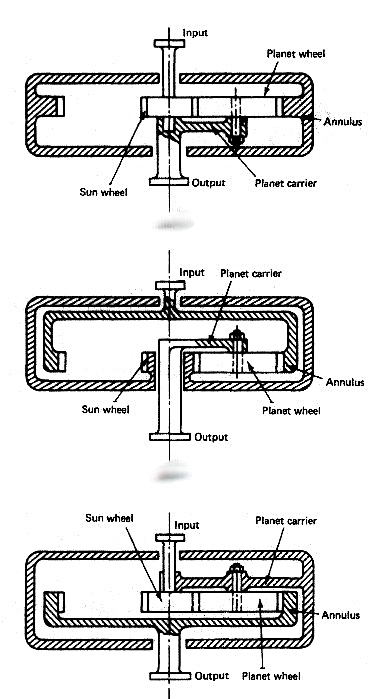
steam turbine epicyclic gearing

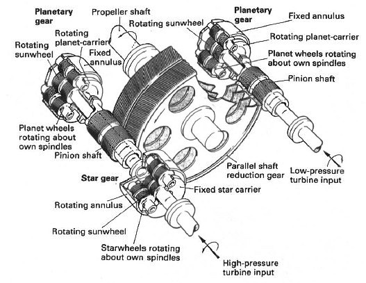
Fig: Steam turbine epicyclic gearing


Epicyclic gearing

This is a system of gears where one or more wheels travel around the outside or inside of another wheel whose axis is fixed. The different arrangements are known as planetary gear, solar gear and star gear

(Figure above). The wheel on the principal axis is called the sun wheel. The wheel whose centre revolves around the principal axis is the planet wheel. An internal-teeth gear which meshes with the planet wheel is called the annulus. The different arrangements of fixed arms and sizing of the sun and planet wheels provide a variety of different reduction ratios. Steam turbine gearing may be double or triple reduction and will be a combination from input to output of star and planetary modes in conjunction with helical gearing (Figure below).


Turbine reduction system

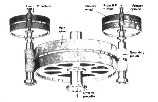
Fig: Turbine reduction gear


Helical gearing

Single or double reduction systems may be used, although double reduction is more usual. With single reduction the turbine drives a pinion with a small number of teeth and this pinion drives the main wheel which is directly coupled to the propeller shaft. With double reduction the turbine drives a primary pinion which drives a primary wheel. The primary wheel drives, on the same shaft, a secondary pinion which drives the main wheel. The main wheel is directly coupled to the propeller shaft. A double reduction gearing system is shown in Figure below.

Turbine double reduction system

Fig: Turbine double reduction system


All modern marine gearing is of the double helical type. Helical means that the teeth form part of a helix on the periphery of the pinion or gear wheel. This means that at any time several teeth are in contact and thus the spread and transfer of load is much smoother. Double helical refers to the use of two wheels or pinions on each shaft with the teeth cut in opposite directions. This is because a single set of meshing helical teeth would produce a sideways force, moving the gears out of alignment. The double set in effect balances out this sideways force. The gearing system shown in Figure is double helical.

Lubrication of the meshing teeth is from the turbine lubricating oil supply. Sprayers are used to project oil at the meshing points both above and below and are arranged along the length of the gear wheel.


Flexible coupling

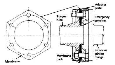
A flexible coupling is always fitted between the turbine rotor and the gearbox pinion. It permits slight rotor and pinion misalignment as well as allowing for axial movement of the rotor due to expansion. Various designs of flexible coupling are in use using teeth, flexible discs, membranes, etc.

Turbine flexible coupling

Fig: Turbine flexible coupling


The membrane-type flexible coupling shown in Figure above is made up of a torque tube, membranes and adaptor plates. The torque tube fits between the turbine rotor and the gearbox pinion. The adaptor plates are spigoted and dowelled onto the turbine and pinion flanges and the membrane plates are bolted between the torque tube and the adaptor plates. The flexing of the membrane plates enables axial and transverse movement to take place. The torque tube enters the adaptor plate with a clearance which will provide an emergency centring should the membranes fail. The bolts in their clearance holes would provide the continuing drive until the shaft could be stopped.


Turning gear

The turning gear on a turbine installation is a reversible electric motor driving a gearwheel which meshes into the high-pressure turbine primary pinion. It is used for gearwheel and turbine rotation during maintenance or when warming-through prior to manoeuvring. 

Steam turbines - operating principle

Steam turbines  - operating principle 


Steam turbines 

The steam turbine has until recently been the first choice for very large power marine propulsion units. Its advantages of little or no vibration, low weight, minimal space requirements and low maintenance costs are considerable. Furthermore a turbine can be provided for any power rating likely to be required for marine propulsion. However, the higher specific fuel consumption when compared with a diesel engine offsets these advantages, although refinements such as reheat have narrowed the gap.

steam turbine

Fig: Energy conversion in a steam turbine


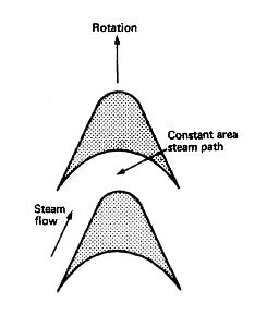
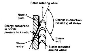
The steam turbine is a device for obtaining mechanical work from the energy stored in steam. Steam enters the turbine with a high energy content and leaves after giving up most of it. The high-pressure steam from the boiler is expanded in nozzles to create a high-velocity jet of steam. The nozzle acts to convert heat energy in the steam into kinetic energy. This jet is directed into blades mounted on the periphery of a wheel or disc (Figure above). 

The steam does not 'blow the wheel around'. The shaping of the blades causes a change in direction and hence velocity of the steam jet. Now a change in velocity for a given mass flow of steam will produce a force which acts to turn the turbine wheel, i.e. mass flow of steam (kg/s) x change in velocity (m/s) = force (kgm/s2).

This is the operating principle of all steam turbines, although the arrangements may vary considerably. The steam from the first set of blades then passes to another set of nozzles and then blades and so on along the rotor shaft until it is finally exhausted. Each set comprising nozzle and blades is called a stage. 


Impulse steam turbine and reaction steam turbine - operating principle 


Steam turbines 


steam turbine

Fig: Energy conversion in a steam turbine


The steam turbine is a device for obtaining mechanical work from the energy stored in steam. There are two main types of turbine, the 'impulse' and the 'reaction'. The names refer to the type of force which acts on the blades to turn the turbine wheel.

Impulse blading

Fig: Impulse blading


Impulse turbine 

The impulse arrangement is made up of a ring of nozzles followed by a ring of blades. The high-pressure, high-energy steam is expanded in the nozzle to a lower-pressure, high-velocity jet of steam. This jet of steam is directed into the impulse blades and leaves in a different direction . The changing direction and therefore velocity produces an impulsive force which mainly acts in the direction of rotation of the turbine blades. There is only a very small end thrust on the turbine shaft.


Reaction blading

Fig: Reaction blading

Reaction blading 

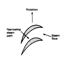
The reaction arrangement is made up of a ring of fixed blades attached to the casing, and a row of similar blades mounted on the rotor, i.e. moving blades . The blades are mounted and shaped to produce a narrowing passage which, like a nozzle, increases the steam velocity. This increase in velocity over the blade produces a reaction force which has components in the direction of blade rotation and also along the turbine axis. There is also a change in velocity of the steam as a result of a change in direction and an impulsive force is also produced with this type of blading. The more correct term for this blade arrangement is 'impulse-reaction'.


Cross compound steam turbine arrangement 


What is Compounding

Compounding is the splitting up, into two or more stages, of the steam pressure or velocity change through a turbine. Pressure compounding of an impulse turbine is the use of a number of stages of nozzle and blade to reduce progressively the steam pressure. This results in lower or more acceptable steam flow speeds and a better turbine efficiency.

Velocity compounding of an impulse turbine is the use of a single nozzle with an arrangement of several moving blades on a single disc. Between the moving blades are fitted guide blades which are connected to the turbine casing. This arrangement produces a short lightweight turbine with a poorer efficiency which would be acceptable in, for example, an astern turbine.

The two arrangements may be combined to give what is called 'pressure-velocity compounding'. The reaction turbine as a result of its blade arrangement changes the steam velocity in both fixed and moving blades with consequent gradual steam pressure reduction. Its basic arrangement therefore provides compounding.

Cross compound steam turbine arrangement

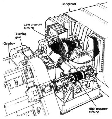
Fig: Cross compound steam turbine arrangement

The term 'cross-compound' is used to describe a steam turbine unit made up of a high pressure and a low pressure turbine . This is the usual main propulsion turbine arrangement. The alternative is a single cylinder unit which would be usual for turbo-generator sets, although some have been fitted for main propulsion service.


Reheat

Reheating is a means of improving the thermal efficiency of the complete turbine plant. Steam, after expansion in the high-pressure turbine, is returned to the boiler to be reheated to the original superheat temperature. It is then returned to the turbine and further expanded through any remaining stages of the high-pressure turbine and then the low-pressure turbine.


sewage treatment plant working principles

Sewage treatment on board- biological and chemical sewage treatment plant working principles 


Sewage treatment on board


The discharge of untreated sewage in controlled or territorial waters is usually banned by legislation. International legislation is in force to cover any sewage discharges within specified distances from land. As a result, and in order to meet certain standards all new ships have sewage treatment plants installed.

Untreated sewage as a suspended solid is unsightly. In order to break down naturally, raw sewage must absorb oxygen. In excessive amounts it could reduce the oxygen content of the water to the point where fish and plant life would die. Pungent smells are also associated with sewage as a result of bacteria which produce hydrogen sulphide gas. Particular bacteria present in the human intestine known as E, coli are also to be found in sewage. The E. coli count in a measured sample of water indicates the amount of sewage present.

Two particular types of sewage treatment plant are in use, employing either chemical or biological methods. The chemical method is basically a storage tank which collects solid material for disposal in permitted areas or to a shore collection facility. The biological method treats the sewage so that it is acceptable for discharge inshore.


Chemical sewage treatment

This system minimises the collected sewage, treats it and retains it until it can be discharged in a decontrolled area, usually well out to sea. Shore receiving facilities may be available in some ports to take this retained sewage.

This system must therefore collect and store sewage produced while the ship is in a controlled area. The liquid content of the system is reduced, where legislation permits, by discharging wash basins, bath and shower drains straight overboard. Any liquid from water closets is treated and used as flushing water for toilets. The liquid must be treated such that it is acceptable in terms of smell and appearance. 

Various chemicals are added at different points for odour and colour removal and also to assist breakdown and sterilisation. A comminutor is used to physically break up the sewage and assist the chemical breakdown process. Solid material settles out in the tank and is stored prior to discharge into the sullage tank: the liquid is recycled for flushing use. Tests must be performed daily to check the chemical dosage rates. This is to prevent odours developing and also to avoid corrosion as a result of high levels of alkalinity.

Biological sewage treatment

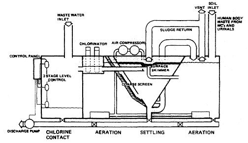
Fig:Biological sewage treatment plant 


Biological sewage treatment

The biological system utilises bacteria to completely break down the sewage into an acceptable substance for discharge into any waters. The extended aeration process provides a climate in which oxygen-loving bacteria multiply and digest the sewage, converting it into a sludge. These oxygen-loving bacteria are known as aerobic.

The treatment plant uses a tank which is divided into three watertight compartments: an aeration compartment, settling compartment and a chlorine contact compartment . 

The sewage enters the aeration compartment where it is digested by aerobic bacteria and micro-organisms, whose existence is aided by atmospheric oxygen which is pumped in. The sewage then flows into the settling compartment where the activated sludge is settled out. The clear liquid flows to the chlorinator and after treatment to kill any remaining bacteria it is discharged. Tablets are placed in the chlorinator and require replacement as they are used up. The activated sludge in the settling tank is continuously recycled and builds up, so that every two to three months it must be partially removed. This sludge must be discharged only in a decontrolled area. 

Wednesday, January 26, 2011

BALANCED RUDDER


Description

Before the balanced rudder, all ships employed a rudder that was a simple flat piece of wood or metal, situated at the after end of the hull and hinged at the forward end, which could be angled to one side or the other to deflect the water passing it and hence provide an impulse to turn the ship. This required the exertion of significant force, as the passage of the water past the rudder tended to force it into a straight line in conformity with the flow.
The concept of a balanced rudder involved the shifting of the centre of rotation of the rudder to point approximately 1/2 of the way from the forward end to the after end. This meant that when the rudder was turned, the flow of water past the ship actively worked on the forward third to increase the angle of deflection, whereas the same flow acted on the after 1/2 to reduce the angle.
The mechanics of fluid dynamics produced a solution in which the turning force applied in one direction on the rudder by the passing fluid was balanced by the turning force applied in the other direction, allowing the rudder to be moved with only limited mechanical resistance.
The balanced rudder was soon adopted by the fledgling aircraft industry in the early 20th century, which often made use of the horn balance, in which a section of the rudder, usually at the top of the vertical stabiliser, projected into the airstream. Two illustrations of aircraft rudders published by Flight Magazine in 1920,[1] illustrate both the conventional balanced rudder (at lower left on the Short Swallow) and with a large 'horn' (at left centre, in this case in the form of a semicircle, on the 'Short Sporting Type').
File:Rudder(Ordinary,Hanging, Balanced,Semi-Balanced,Unbalanced).PNG
Different types of balanced rudder shown: 3 balanced, 4 semi-balanced, 5 non-balanced (hinged about axis 'A')

How Is Water In Double Bottom Tanks & Bilge Spaces Handled?


Introduction

We have learnt about the pipline arrangement on ships and also tips on how to identify pipeline systems used for different purposes such as lubricating oil, sea water and so forth. In this article we will study the general piping arrangement on a ship relating to bilge pipes as well as DB tank pipe fitting arrangement. Basically these types of piping systems are used for ballasting/deballasting operations, flood water removal and bilge water handling.

Piping Arrangement

Bilge Piping ArrangementRegarding the bilge pipes, you can see figure 1 below. As you will notice, there is an elaborate system of pipes which run through the bilges in all areas of the ship. The symbols for the various objects shown in the diagram are as follows

  • Inverted triangle – mud boxes
  • Circles – non return bilge valves
  • Circles with a line diametrically across it – flap valves non return
  • Thick dots – sounding pipes

The bilge injection valve can be seen towards the bottom of the image somewhere towards the left hand side of the centre portion. The various pumps shown in the picture consist of

  • Bilge pump
  • General Service pump
  • Sanitary pump
  • Ballast pump

The various areas of the ship have means for suction through some pump or the other and most of the pumps and pipes are interconnected and can be used appropriately as the situation demands either in routine operations or emergency situations.

Similarly the diagram in figure 2 shows the piping arrangement for the deep tanks of the ship, which are also known as double bottom or db tanks. These are mainly used for ballasting procedures. If you are wondering why are these pipelines not in common which will save cost and equipment; I must tell you that this is mandatory as per IMO regulations that the bilge pipes cannot pass through the DB tanks and they have to be a part of a separate system. In case there is a common pump it should have appropriate isolating arrangement in terms of non return valves or one way cocks.
DB Tank Pipeline System
One such is shown in the diagram and you can notice that it has two pipe connections to it, one for suction and the other for discharge of the sea water. Similarly the ballast pumps can either take water from the sea for delivery to the deep tanks or vice versa depending on whether the ballasting or deballasting operation is required to be performed.

Important

An important rule which always needs to be followed in laying down the ballast piping arrangement is that there should not be any possibility of the ballast water to gain access to areas which carry dry cargo. Similarly regulations also state that there should be ample provision to ensure that the water ballast and the fuel of the ship are always isolated from one another.

Last but not least, I must say that since there are so many types of ships which are used for different purposes, it is not easy to generalize the piping systems in all of them. The above described features fit most aptly on cargo vessels though other type of ships are not much different at least in principle if not in the actual layout of the pipelines.


Read more: http://www.brighthub.com/engineering/marine/articles/48582.aspx#ixzz1C9gnI5Ko

Monday, January 24, 2011

Double hull


double hull is a ship hull design and construction method where the bottom and sides of the ship have two complete layers of watertight hull surface: one outer layer forming the normal hull of the ship, and a second inner hull which is some distance inboard, typically by a few feet, which forms a redundant barrier to seawater in case the outer hull is damaged and leaks.
The space between the two hulls is often used for storage of fuel or ballast water.
Double hulls are a more extensive safety measure than double bottoms, which have two hull layers only in the bottom of the ship but not the sides.
In low-energy casualties, double hulls can prevent flooding beyond the penetrated compartment. In high-energy casualties, however, the distance to the inner hull is not sufficient and the inner compartment is penetrated as well.
Double hulls or double bottoms have been required in all passenger ships for decades as part of theSafety Of Life At Sea or SOLAS Convention.[citation needed]
File:DoubleBottomDoubleHull.png
One of the disadvantages of a double hull is that the stability of a ship can be less than that of a single hull. Because the double hull raises the centre of gravity, the metacentric height is reduced.

Sunday, January 23, 2011

Under water survey

GUIDE FOR THE CLASS NOTATION
UNDERWATER INSPECTION IN LIEU OF
DRYDOCKING (UWILD)
APRIL 2007
American Bureau of Shipping
Incorporated by Act of Legislature of
the State of New York 1862
Copyright
American Bureau of Shipping
ABS Plaza
16855 Northchase Drive
Houston, TX 77060 USA
© 2007
ABS
GUIDE FOR THE CLASS NOTATION UNDERWATER INSPECTION IN LIEU OF DRYDOCKING (UWILD) . 2007 ii
Foreword
Foreword
This Guide aims to consolidate the classification requirements, currently specified in Appendix 7-A-1
of the ABS
response to the industry and market demands.
This consolidated
(UWILD)
as specified in Appendix 7-A-1 of the ABS
improve the usefulness as a Guide, some reorganization of the text and additional information are
provided.
Rules for Survey After Construction (Part 7) for the optional class notation (UWILD) inGuide for the Class Notation Underwater Inspection In Lieu of Drydocking Surveyis prepared for the user’s convenience, but intends to change the current applicable requirementsRules for Survey After Construction (Part 7). In order to
ABS
GUIDE FOR THE CLASS NOTATION UNDERWATER INSPECTION IN LIEU OF DRYDOCKING (UWILD) . 2007 iii
Table of Contents
GUIDE FOR THE CLASS NOTATION
UNDERWATER INSPECTION IN LIEU OF
DRYDOCKING (UWILD)
CONTENTS
SECTION 1 Introduction ............................................................................1
1 Scope and Application........................................................... 1
3 Approval Procedure............................................................... 1
5 Governmental Regulations.................................................... 1
FIGURE 1 Approval Procedures for UWILD Class Notation ........ 1
SECTION 2 Conditions and Procedures .................................................. 2
1 General.................................................................................. 2
3 Conditions.............................................................................. 2
3.1 Limitations .........................................................................2
3.3 Existing Outstanding Recommendations...........................2
3.5 Thickness Measurements and Nondestructive Testing .....3
3.7 Tailshaft Surveys...............................................................3
3.9 Plans and Data..................................................................3
3.11 Underwater Conditions......................................................3
5 Physical Features.................................................................. 3
5.1 Stern Bearing ....................................................................4
5.3 Rudder Bearings ...............................................................4
5.5 Sea Suctions .....................................................................4
5.7 Sea Valves ........................................................................4
7 Procedures ............................................................................ 4
7.1 Exposed Areas..................................................................4
7.3 Underwater Areas .............................................................4
7.5 Damage Areas ..................................................................5
7.7 Planning ............................................................................5
9 Alternatives............................................................................ 5
11 Maintenance of UWILD Class Notation................................. 5
ABS
GUIDE FOR THE CLASS NOTATION UNDERWATER INSPECTION IN LIEU OF DRYDOCKING (UWILD) . 2007 1
Section 1: Introduction
S E C T I O N
 
1 Scope and Application
A request for Underwater Inspection may be accepted as an alternative to Drydocking Inspection
provided that all arrangements and equipment meet the requirements specified in this Guide.
For vessels 15 years of age or over and subject to the Enhanced Survey Program (ESP), Underwater
Inspections in Lieu of Drydocking (UWILD) are not permitted as an alternate Drydocking Surveys.

3 Approval Procedure

An ABS optional notation,
to a vessel in full compliance with the requirements as specified in this Guide. The entire procedure
for assignment of the
UWILD, for Underwater Inspection in Lieu of Drydocking, is to be assignedUWILD notation is shown in Section 1, Figure 1.

5 Governmental Regulations

The requirements specified in this Guide are for classification only. Flag Administrations may have
specific regulations for Underwater Surveys in Lieu of Drydocking, including requirements for enrollment,
hull markings, extent of visibility and procedures for older vessels.

FIGURE 1
Approval Procedures for UWILD Class Notation
UWILD
1.Request for
(by Owner/Operator)
2.Preparation and submission of plans as
required by 2/3.9, 2/5
3.Initial survey of underwater hull markings
and other means of orienting the diver
during new construction
OR
An out-of-water drydocking (Existing Vessel)
4.Issue certification of compliance
with
UWILD NotationUWILD requirements
ABS
GUIDE FOR THE CLASS NOTATION UNDERWATER INSPECTION IN LIEU OF DRYDOCKING (UWILD) . 2007 2
Section 2: Conditions and Procedures
S E C T I O N
2 Conditions and Procedures
1 General
At the request of the Owner, the Bureau may consider Underwater Inspection in Lieu of Drydocking
Survey provided all arrangements and conditions meet the requirements of the Guide.
All requests for Underwater Inspection in Lieu of Drydocking Survey are to be forwarded to the
applicable ABS Divisional Assistant Chief Surveyor’s Office for review and authorization.
Underwater inspection is to be carried out by a qualified diver under the surveillance of the attending
Surveyor. The diver is to be employed by a firm approved by the Bureau as a service supplier.
The Surveyor is to be satisfied with the method of pictorial representation, and a good two-way
communication between the Surveyor and divers is to be provided.
If the Underwater Inspection reveals damage or deterioration that requires further attention, the Surveyor
may require that the vessel be drydocked in order to undertake a detailed survey and necessary repairs.
The extent of the underwater inspection is to be sufficient to include all items which would normally
be examined if the vessel was on drydock, some of which are listed in 2/7.3.
The following Subsections describe the conditions and procedures under which a properly conducted
underwater inspection may be credited as an alternative of Drydocking Survey.
3 Conditions
3.1 Limitations
i) Non-ESP
subject to special consideration based on the following review and examination before being
permitted to have underwater inspection:
vessels 15 years of age or over applying to maintain their UWILD notation are
Review of vessel’s records to ensure that no unusual repairs have been required/made
Internal examination of representative tanks and cargo holds
ii)
where there is record or indication of abnormal deterioration, existing recommendation, or
damage to underwater body, rudder, or propeller.

Underwater Inspection In Lieu of Drydocking Survey (UWILD) may be restricted or limited
3.3 Existing Outstanding Recommendations
UWILD may not be applicable if there are outstanding recommendations for repairs to propeller, rudder,
stern frame, underwater structure, or sea valves. It may also be inapplicable if damage affecting the
fitness of the vessel is found during the course of the survey.
 
3.5 Thickness Measurements and Nondestructive Testing
Underwater or internal thickness measurements of suspect areas may be required in conjunction with
the underwater inspection. Means for underwater nondestructive testing may also be required for fracture
detection.
Note
drydock in conjunction with visual inspection of the bottom plating by the Surveyor.
Thickness measurements of the hull underwater body, as required for Special Periodical Survey, are to be taken at
3.7 Tailshaft Surveys
Tailshaft Surveys are not covered by this Guide and are to be dealt with in accordance with Chapter 5
of the ABS
Rules for Survey After Construction (Part 7) and other applicable Rules.
3.9 Plans and Data
Plans showing the following items are to be submitted to the attending Surveyor, together with the
proposed inspection procedures for review, well in advance of the inspection.
i)
bottom plugs, appendages and all underwater openings.
Location of bottom shell seams and butts (Shell Expansion), including any doublers, straps,
ii)
specific areas of plating, (e.g., locations of bulkheads or tanks) sea suction and discharge
openings, propeller blades and rudder surfaces. Such preparations may include a weld bead
grid system on the hull, a contrasting color coating system, a movable grid, an acoustic locating
system, or any other arrangement that is satisfactory to the Surveyor.
Hull markings or other means to orient the diver and identifying photographs, which entail
iii)
means of access to sea chests to inspect the external side of hull connections and sea values,
to rudder bearings to determine clearances of rudder bearings or to propeller shaft strut and
stern bearings.
Reference data and instructions to the diver for any necessary underwater operations such as
vi)
scantlings for the underwater body.
Most recent gaugings and gauging report from last Special Periodical Survey and the as-built
3.11 Underwater Conditions
i)
permit meaningful examination and photography by the diver. “Sufficiently clean” is taken to
mean that sections of the underwater body, including flat keel plating forward, amidships and
aft, are cleaned to the extent that the Surveyor can determine the condition of the plating, the
welding and the coating. Additional cleaning may be necessary. Overall or spot cleaning may
be required at the discretion of the attending Surveyor.
The vessel’s underwater body is to be sufficiently clean and the sea water is clear enough to
ii)
with weak tidal streams and currents and with the vessel at light draft.
Where possible, the underwater examination should be carried out in protected waters, preferably
5 Physical Features
The following physical features are to be incorporated into the vessel’s design in order to facilitate the
underwater inspection. When verified, they are to be noted in the vessel’s records for reference at
subsequent surveys.
Section 2 Conditions and Requirements
ABS
GUIDE FOR THE CLASS NOTATION UNDERWATER INSPECTION IN LIEU OF DRYDOCKING (UWILD) . 2007 4
5.1 Stern Bearing
i)
bearings and to verify that the clearance or weardown is within limits on the stern bearing
Means are to be provided to ascertain that the seal assembly remains intact on oil-lubricated
ii)
including accurate oil-loss records and a check of the oil for contamination by sea water or
white metal and/or oil sample reports (considerations are to be included in the proposals for
UWILD). For wood or rubber bearings, an opening in the top of the rope guard and a suitable
gauge or wedge is sufficient for checking the clearance.
For oil-lubricated bearings, this may require the review of operating history and onboard testing
iii)
checked by external measurements or by the vessel’s wear-down gauge, where the gauge wells
are located outboard of the seals or the vessel can be tipped. For use of the wear-down gauges,
up-to-date records of the base depths are to be maintained onboard the vessel. Whenever the
stainless steel seal sleeve is renewed or machined, the base readings for the wear-down gauge
are to be re-established and noted in the vessel’s records and in the survey report.
Any doubt on wear-down of oil-lubricated metal stern bearings from above is to be further
5.3 Rudder Bearings
Means and access are to be provided to determine the condition and clearance of the rudder bearings,
and verify that all parts of the pintle and gudgeon assemblies are intact and secure. This may require
bolted access plates and a measuring arrangement.
Where it is deemed impractical, clearance verification on the rudder pintle may be dispensed with if
the attending Surveyor is satisfied with the physical condition and securing arrangements of the pintle,
the operating history and the onboard testing. These considerations are to be included in the proposals
for UWILD.
5.5 Sea Suctions
Means are to be provided to enable the diver to confirm that the sea suction openings are clear. Hinged
sea suction grids may be used to facilitate this operation.
5.7 Sea Valves
Sea valves and their attachment to sea chests are to be examined externally, including expansion pieces
in sea water cooling and circulating systems.
7 Procedures
7.1 Exposed Areas
An examination of the outside of the shell plating above the waterline and exposed portions of appendages
(such as propeller, rudder and rudder bearings) is to be carried out by the attending Surveyor. Means
are to be provided to enable the Surveyor to accomplish this visual inspection.
7.3 Underwater Areas
An examination of the entire vessel below the waterline is to be carried out by an ABS-approved diver
using closed-circuit television with two-way communication. The progress of the dive is to be
monitored by the onboard Surveyor as required, or is to be photographically documented, or both,
depending on the age and type of vessel. Items that must be recorded on the tape/photograph include
but are not limited to:
i)
Time at which dive commences
ii)
iii)
Time viewed
iv)
Conditions of hull markings
v)
Random areas of plating
vi)
All sea chests
vii)
All inlets and discharges
viii)
Rudder
ix)
Pintles
x)
Propeller
xi)
The above examination is to be supplemented by the diver’s report describing and attesting to the
conditions found. A copy of this report and pertinent photographs are to be submitted to the attending
Surveyor. Copies are also to be retained onboard.
Time and point of completion of the dive;
7.5 Damage Areas
Damage and corrosion areas are to be taped/photographed. Internal examination or thickness gauging
of such locations may be necessary, as determined by the attending Surveyor. Means are to be provided
for orienting and identifying underwater surfaces in photographs, as noted in 2/3.9ii).
7.7 Planning
The equipment and procedure for observing and reporting the survey are to be discussed with the
parties involved prior to the UWILD, and suitable time is to be allowed to permit the diving company
to test all equipment beforehand.
9 Alternatives
The Bureau is prepared to consider alternatives to the above guidelines.
11 Maintenance of UWILD Class Notation
For maintenance of the UWILD notation, a vessel’s markings and equipment installed for UWILD are to be satisfactorily verified by the attending Surveyor at each Drydocking.

ABS GUIDE FOR THE CLASS NOTATION UNDERWATER INSPECTION IN LIEU OF DRYDOCKING (UWILD) . 2007 5
Point of commencement
1 Introduction