Steam turbines control and protection

Steam turbines control
The steam turbine has until recently been the first choice for very large power marine propulsion units. Its advantages of little or no vibration, low weight, minimal space requirements and low maintenance costs are considerable. Furthermore a turbine can be provided for any power rating likely to be required for marine propulsion. However, the higher specific fuel consumption when compared with a diesel engine offsets these advantages, although refinements such as reheat have narrowed the gap.
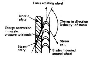
Fig: Energy conversion in a steam turbine
The valves which admit steam to the ahead or astern turbines are known as 'manoeuvring valves'. There are basically three valves, the ahead, the astern and the guarding or guardian valve. The guardian valve is an astern steam isolating valve. These valves are hydraulically operated by an independent system employing a main and standby set of pumps. Provision is also made for hand operation in the event of remote control system failure.
Operation of the ahead manoeuvring valve will admit steam to the main nozzle box. Remotely operated valves are used to open up the remaining nozzle boxes for steam admission as increased power is required. A speed-sensitive control device acts on the ahead manoeuvring valve to hold the turbine speed constant at the desired value. Operation of the astern manoeuvring valve will admit steam to the guardian valve which is opened in conjunction with the astern valve. Steam is then admitted to the astern turbines.
Turbine protection
A turbine protection system is provided with all installations to prevent damage resulting from an internal turbine fault or the malfunction of some associated equipment. Arrangements are made in the system to shut the turbine down using an emergency stop and solenoid valve. Operation of this device cuts off the hydraulic oil supply to the manoeuvring valve and thus shuts off steam to the turbine. This main trip relay is operated by a number of main fault conditions which are;
1. Low lubricating oil pressure.
2. Overspeed.
3. Low condenser vacuum.
4. Emergency stop.
5. High condensate level in condenser.
6. High or low boiler water level.
Other fault conditions which must be monitored and form part of a total protection system are:
1. HP and LP rotor eccentricity or vibration.
2. HP and LP turbine differential expansion, i.e. rotor with respect to casing.
3. HP and LP thrust bearing weardown.
4. Main thrust bearing weardown.
5. Turning gear engaged (this would prevent starting of the turbine).
Such 'turbovisory' systems, as they may be called, operate in two ways. If a tendency towards a dangerous condition is detected a first stage alarm is given. This will enable corrective action to be taken and the turbine is not shut down. If corrective action is not rapid, is unsuccessful, or a main fault condition quickly arises, the second stage alarm is given and the main trip relay is operated to stop the turbine.
Steam turbines gearing arrangement
Turbine gearing
Steam turbines operate at speeds up to 6000rev/min. Medium-speed diesel engines operate up to about 750rev/min. The best propeller speed for efficient operation is in the region of 80 to lOOrev/min. The turbine or engine shaft speed is reduced to that of the propeller by the use of a system of gearing. Helical gears have been used for many years and remain a part of most systems of gearing. Epicyclic gears with their compact, lightweight, construction are being increasingly used in marine transmissions.
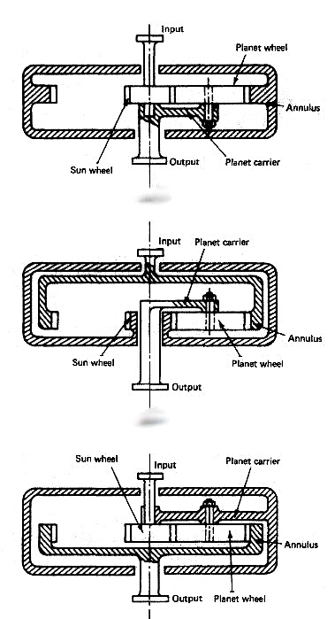
Fig: Steam turbine epicyclic gearing
Epicyclic gearing
This is a system of gears where one or more wheels travel around the outside or inside of another wheel whose axis is fixed. The different arrangements are known as planetary gear, solar gear and star gear
(Figure above). The wheel on the principal axis is called the sun wheel. The wheel whose centre revolves around the principal axis is the planet wheel. An internal-teeth gear which meshes with the planet wheel is called the annulus. The different arrangements of fixed arms and sizing of the sun and planet wheels provide a variety of different reduction ratios. Steam turbine gearing may be double or triple reduction and will be a combination from input to output of star and planetary modes in conjunction with helical gearing (Figure below).
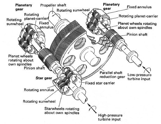
Fig: Turbine reduction gear
Helical gearing
Single or double reduction systems may be used, although double reduction is more usual. With single reduction the turbine drives a pinion with a small number of teeth and this pinion drives the main wheel which is directly coupled to the propeller shaft. With double reduction the turbine drives a primary pinion which drives a primary wheel. The primary wheel drives, on the same shaft, a secondary pinion which drives the main wheel. The main wheel is directly coupled to the propeller shaft. A double reduction gearing system is shown in Figure below.
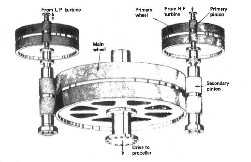
Fig: Turbine double reduction system
All modern marine gearing is of the double helical type. Helical means that the teeth form part of a helix on the periphery of the pinion or gear wheel. This means that at any time several teeth are in contact and thus the spread and transfer of load is much smoother. Double helical refers to the use of two wheels or pinions on each shaft with the teeth cut in opposite directions. This is because a single set of meshing helical teeth would produce a sideways force, moving the gears out of alignment. The double set in effect balances out this sideways force. The gearing system shown in Figure is double helical.
Lubrication of the meshing teeth is from the turbine lubricating oil supply. Sprayers are used to project oil at the meshing points both above and below and are arranged along the length of the gear wheel.
Flexible coupling
A flexible coupling is always fitted between the turbine rotor and the gearbox pinion. It permits slight rotor and pinion misalignment as well as allowing for axial movement of the rotor due to expansion. Various designs of flexible coupling are in use using teeth, flexible discs, membranes, etc.
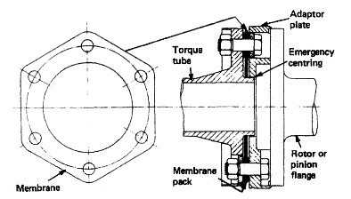
Fig: Turbine flexible coupling
The membrane-type flexible coupling shown in Figure above is made up of a torque tube, membranes and adaptor plates. The torque tube fits between the turbine rotor and the gearbox pinion. The adaptor plates are spigoted and dowelled onto the turbine and pinion flanges and the membrane plates are bolted between the torque tube and the adaptor plates. The flexing of the membrane plates enables axial and transverse movement to take place. The torque tube enters the adaptor plate with a clearance which will provide an emergency centring should the membranes fail. The bolts in their clearance holes would provide the continuing drive until the shaft could be stopped.
Turning gear
The turning gear on a turbine installation is a reversible electric motor driving a gearwheel which meshes into the high-pressure turbine primary pinion. It is used for gearwheel and turbine rotation during maintenance or when warming-through prior to manoeuvring.
Steam turbines - operating principle
Steam turbines
The steam turbine has until recently been the first choice for very large power marine propulsion units. Its advantages of little or no vibration, low weight, minimal space requirements and low maintenance costs are considerable. Furthermore a turbine can be provided for any power rating likely to be required for marine propulsion. However, the higher specific fuel consumption when compared with a diesel engine offsets these advantages, although refinements such as reheat have narrowed the gap.
Fig: Energy conversion in a steam turbine
The steam turbine is a device for obtaining mechanical work from the energy stored in steam. Steam enters the turbine with a high energy content and leaves after giving up most of it. The high-pressure steam from the boiler is expanded in nozzles to create a high-velocity jet of steam. The nozzle acts to convert heat energy in the steam into kinetic energy. This jet is directed into blades mounted on the periphery of a wheel or disc (Figure above).
The steam does not 'blow the wheel around'. The shaping of the blades causes a change in direction and hence velocity of the steam jet. Now a change in velocity for a given mass flow of steam will produce a force which acts to turn the turbine wheel, i.e. mass flow of steam (kg/s) x change in velocity (m/s) = force (kgm/s2).
This is the operating principle of all steam turbines, although the arrangements may vary considerably. The steam from the first set of blades then passes to another set of nozzles and then blades and so on along the rotor shaft until it is finally exhausted. Each set comprising nozzle and blades is called a stage.
Impulse steam turbine and reaction steam turbine - operating principle
Steam turbines
Fig: Energy conversion in a steam turbine
The steam turbine is a device for obtaining mechanical work from the energy stored in steam. There are two main types of turbine, the 'impulse' and the 'reaction'. The names refer to the type of force which acts on the blades to turn the turbine wheel.
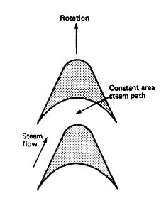
Fig: Impulse blading
Impulse turbine
The impulse arrangement is made up of a ring of nozzles followed by a ring of blades. The high-pressure, high-energy steam is expanded in the nozzle to a lower-pressure, high-velocity jet of steam. This jet of steam is directed into the impulse blades and leaves in a different direction . The changing direction and therefore velocity produces an impulsive force which mainly acts in the direction of rotation of the turbine blades. There is only a very small end thrust on the turbine shaft.
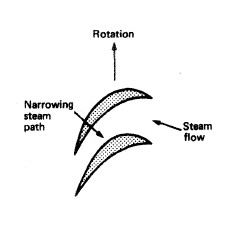
Fig: Reaction blading
Reaction blading
The reaction arrangement is made up of a ring of fixed blades attached to the casing, and a row of similar blades mounted on the rotor, i.e. moving blades . The blades are mounted and shaped to produce a narrowing passage which, like a nozzle, increases the steam velocity. This increase in velocity over the blade produces a reaction force which has components in the direction of blade rotation and also along the turbine axis. There is also a change in velocity of the steam as a result of a change in direction and an impulsive force is also produced with this type of blading. The more correct term for this blade arrangement is 'impulse-reaction'.
Cross compound steam turbine arrangement
What is Compounding
Compounding is the splitting up, into two or more stages, of the steam pressure or velocity change through a turbine. Pressure compounding of an impulse turbine is the use of a number of stages of nozzle and blade to reduce progressively the steam pressure. This results in lower or more acceptable steam flow speeds and a better turbine efficiency.
Velocity compounding of an impulse turbine is the use of a single nozzle with an arrangement of several moving blades on a single disc. Between the moving blades are fitted guide blades which are connected to the turbine casing. This arrangement produces a short lightweight turbine with a poorer efficiency which would be acceptable in, for example, an astern turbine.
The two arrangements may be combined to give what is called 'pressure-velocity compounding'. The reaction turbine as a result of its blade arrangement changes the steam velocity in both fixed and moving blades with consequent gradual steam pressure reduction. Its basic arrangement therefore provides compounding.
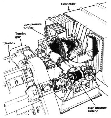
Fig: Cross compound steam turbine arrangement
The term 'cross-compound' is used to describe a steam turbine unit made up of a high pressure and a low pressure turbine . This is the usual main propulsion turbine arrangement. The alternative is a single cylinder unit which would be usual for turbo-generator sets, although some have been fitted for main propulsion service.
Reheat
Reheating is a means of improving the thermal efficiency of the complete turbine plant. Steam, after expansion in the high-pressure turbine, is returned to the boiler to be reheated to the original superheat temperature. It is then returned to the turbine and further expanded through any remaining stages of the high-pressure turbine and then the low-pressure turbine.
Sewage treatment on board- biological and chemical sewage treatment plant working principles
Sewage treatment on board
The discharge of untreated sewage in controlled or territorial waters is usually banned by legislation. International legislation is in force to cover any sewage discharges within specified distances from land. As a result, and in order to meet certain standards all new ships have sewage treatment plants installed.
Untreated sewage as a suspended solid is unsightly. In order to break down naturally, raw sewage must absorb oxygen. In excessive amounts it could reduce the oxygen content of the water to the point where fish and plant life would die. Pungent smells are also associated with sewage as a result of bacteria which produce hydrogen sulphide gas. Particular bacteria present in the human intestine known as E, coli are also to be found in sewage. The E. coli count in a measured sample of water indicates the amount of sewage present.
Two particular types of sewage treatment plant are in use, employing either chemical or biological methods. The chemical method is basically a storage tank which collects solid material for disposal in permitted areas or to a shore collection facility. The biological method treats the sewage so that it is acceptable for discharge inshore.
Chemical sewage treatment
This system minimises the collected sewage, treats it and retains it until it can be discharged in a decontrolled area, usually well out to sea. Shore receiving facilities may be available in some ports to take this retained sewage.
This system must therefore collect and store sewage produced while the ship is in a controlled area. The liquid content of the system is reduced, where legislation permits, by discharging wash basins, bath and shower drains straight overboard. Any liquid from water closets is treated and used as flushing water for toilets. The liquid must be treated such that it is acceptable in terms of smell and appearance.
Various chemicals are added at different points for odour and colour removal and also to assist breakdown and sterilisation. A comminutor is used to physically break up the sewage and assist the chemical breakdown process. Solid material settles out in the tank and is stored prior to discharge into the sullage tank: the liquid is recycled for flushing use. Tests must be performed daily to check the chemical dosage rates. This is to prevent odours developing and also to avoid corrosion as a result of high levels of alkalinity.
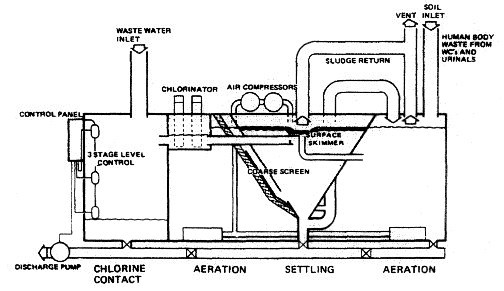
Fig:Biological sewage treatment plant
Biological sewage treatment
The biological system utilises bacteria to completely break down the sewage into an acceptable substance for discharge into any waters. The extended aeration process provides a climate in which oxygen-loving bacteria multiply and digest the sewage, converting it into a sludge. These oxygen-loving bacteria are known as aerobic.
The treatment plant uses a tank which is divided into three watertight compartments: an aeration compartment, settling compartment and a chlorine contact compartment .
The sewage enters the aeration compartment where it is digested by aerobic bacteria and micro-organisms, whose existence is aided by atmospheric oxygen which is pumped in. The sewage then flows into the settling compartment where the activated sludge is settled out. The clear liquid flows to the chlorinator and after treatment to kill any remaining bacteria it is discharged. Tablets are placed in the chlorinator and require replacement as they are used up. The activated sludge in the settling tank is continuously recycled and builds up, so that every two to three months it must be partially removed. This sludge must be discharged only in a decontrolled area.