Turbine gearing
Steam turbines operate at speeds up to 6000rev/min. Medium-speed diesel engines operate up to about 750rev/min. The best propeller speed for efficient operation is in the region of 80 to lOOrev/min. The turbine or engine shaft speed is reduced to that of the propeller by the use of a system of gearing. Helical gears have been used for many years and remain a part of most systems of gearing. Epicyclic gears with their compact, lightweight, construction are being increasingly used in marine transmissions.
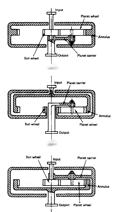
Fig: Steam turbine epicyclic gearing
Epicyclic gearing
This is a system of gears where one or more wheels travel around the outside or inside of another wheel whose axis is fixed. The different arrangements are known as planetary gear, solar gear and star gear
(Figure above). The wheel on the principal axis is called the sun wheel. The wheel whose centre revolves around the principal axis is the planet wheel. An internal-teeth gear which meshes with the planet wheel is called the annulus. The different arrangements of fixed arms and sizing of the sun and planet wheels provide a variety of different reduction ratios. Steam turbine gearing may be double or triple reduction and will be a combination from input to output of star and planetary modes in conjunction with helical gearing (Figure below).
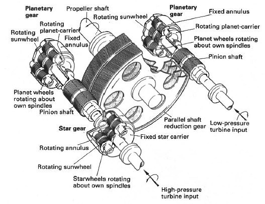
Fig: Turbine reduction gear
Helical gearing
Single or double reduction systems may be used, although double reduction is more usual. With single reduction the turbine drives a pinion with a small number of teeth and this pinion drives the main wheel which is directly coupled to the propeller shaft. With double reduction the turbine drives a primary pinion which drives a primary wheel. The primary wheel drives, on the same shaft, a secondary pinion which drives the main wheel. The main wheel is directly coupled to the propeller shaft. A double reduction gearing system is shown in Figure below.
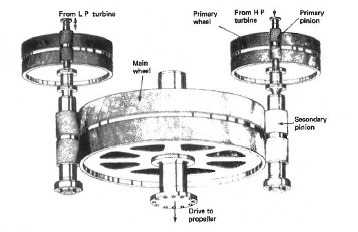
Fig: Turbine double reduction system
All modern marine gearing is of the double helical type. Helical means that the teeth form part of a helix on the periphery of the pinion or gear wheel. This means that at any time several teeth are in contact and thus the spread and transfer of load is much smoother. Double helical refers to the use of two wheels or pinions on each shaft with the teeth cut in opposite directions. This is because a single set of meshing helical teeth would produce a sideways force, moving the gears out of alignment. The double set in effect balances out this sideways force. The gearing system shown in Figure is double helical.
Lubrication of the meshing teeth is from the turbine lubricating oil supply. Sprayers are used to project oil at the meshing points both above and below and are arranged along the length of the gear wheel.
Flexible coupling
A flexible coupling is always fitted between the turbine rotor and the gearbox pinion. It permits slight rotor and pinion misalignment as well as allowing for axial movement of the rotor due to expansion. Various designs of flexible coupling are in use using teeth, flexible discs, membranes, etc.
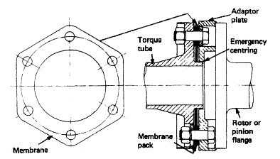
Fig: Turbine flexible coupling
The membrane-type flexible coupling shown in Figure above is made up of a torque tube, membranes and adaptor plates. The torque tube fits between the turbine rotor and the gearbox pinion. The adaptor plates are spigoted and dowelled onto the turbine and pinion flanges and the membrane plates are bolted between the torque tube and the adaptor plates. The flexing of the membrane plates enables axial and transverse movement to take place. The torque tube enters the adaptor plate with a clearance which will provide an emergency centring should the membranes fail. The bolts in their clearance holes would provide the continuing drive until the shaft could be stopped.
Turning gear
The turning gear on a turbine installation is a reversible electric motor driving a gearwheel which meshes into the high-pressure turbine primary pinion. It is used for gearwheel and turbine rotation during maintenance or when warming-through prior to manoeuvring.
Hello, I love reading through your blog, I wanted to leave a little comment to support you and wish you a good continuation. Wish you best of luck for all your best efforts. gear coupling suppliers, gear coupling suppliers in India.
ReplyDeleteHello, I love reading through your blog, I wanted to leave a little comment to support you and wish you a good continuation. Wish you best of luck for all your best efforts. gear coupling manufacturers in India , gear coupling suppliers .
ReplyDeleteHello, I love reading through your blog, I wanted to leave a little comment to support you and wish you a good continuation. Wish you best of luck for all your best efforts. gear coupling manufacturers in India , gear coupling suppliers .
ReplyDelete